Workshop 4 Preview: IMU Alone - Watching It Drift Away
Part 1 of 4: Why Raw IMU Data Isn’t Enough for Robot Navigation
What This Series Covers
ROSCon India 2025 Workshop 4 by Yaanendriya Pvt. Ltd. features hands-on exercises in IMU-Centric Perception. This 4-part preview series takes you through the complete problem domain using the Intel RealSense D435i.
| Part | Stage | Focus | Key Learning |
|---|---|---|---|
| Part 1 (This Post) | IMU Only | Raw IMU problems | Why IMU alone isn’t enough |
| Part 2 | Vision Only | Visual odometry problems | Why vision alone fails |
| Part 3 | Fusion (VIO) | Combining strengths | How fusion solves both |
| Part 4 | Workshop Prep | yDx.M context | What Yaanendriya adds |
We’ll experience the exact problems that motivated professional IMU solutions like Yaanendriya’s yDx.M module. By struggling with these issues firsthand, we’ll deeply appreciate the solutions the workshop will teach.
The D435i: Our IMU Testing Platform
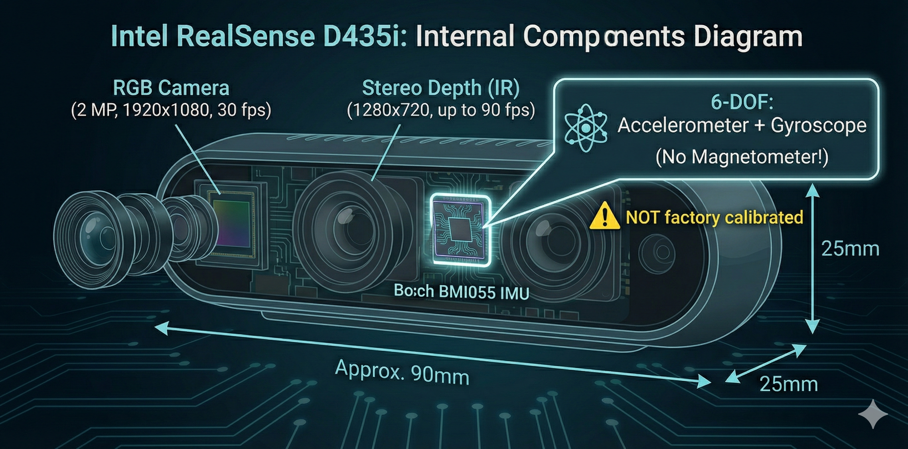
The Intel RealSense D435i combines a depth camera with a built-in 6-DOF IMU (Bosch BMI055). This makes it perfect for experiencing IMU problems before adding vision fusion.
┌─────────────────────────────────────────────────────────────────────────┐
│                      INTEL REALSENSE D435i                              │
│                                                                         │
│    ┌──────────────────────────────────────────────────────────────┐    │
│    │                    Hardware Components                        │    │
│    ├────────────────────┬────────────────────┬────────────────────┤    │
│    │   RGB Camera       │   Stereo Depth     │   IMU (BMI055)     │    │
│    │   1920×1080@30fps  │   1280×720@90fps   │   400 Hz           │    │
│    └────────────────────┴────────────────────┴────────────────────┘    │
│                                                                         │
│    IMU Specs:                                                          │
│    • Accelerometer: ±2/4/8/16G, 12-bit                                │
│    • Gyroscope: ±2000°/s, 16-bit                                      │
│    • Output Rate: Up to 400 Hz                                        │
│    • ⚠️ NOT factory calibrated!                                       │
│    • ⚠️ No magnetometer (6-DOF only)                                  │
│                                                                         │
└─────────────────────────────────────────────────────────────────────────┘
Experiment 1: Raw IMU Has No Orientation!
What You’ll Experience
The first shock: raw IMU data doesn’t include orientation. The sensor outputs acceleration and angular velocity, but not roll-pitch-yaw!
Launch the Container
# Launch Workshop 4 container
./scripts/launch-container.sh 4

# Inside container - start RealSense with IMU enabled
ros2 launch realsense2_camera rs_launch.py \
    enable_gyro:=true \
    enable_accel:=true \
    unite_imu_method:=2
RealSense Launch Output
When you launch, you’ll see output like this:
[INFO] [camera.camera]: Device with name Intel RealSense D435I was found.
[INFO] [camera.camera]: Device Serial No: 317222070886
[INFO] [camera.camera]: Device FW version: 5.13.0.50
[INFO] [camera.camera]: Set ROS param gyro_fps to default: 200
[INFO] [camera.camera]: Set ROS param accel_fps to default: 100
[INFO] [camera.camera]: Starting Sensor: Motion Module
WARNING [ds-calib-parsers.cpp:36] IMU Calibration is not available,
        default intrinsic and extrinsic will be used.
[INFO] [camera.camera]: Open profile: stream_type: Accel(0)Format: MOTION_XYZ32F, FPS: 100
[INFO] [camera.camera]: Open profile: stream_type: Gyro(0)Format: MOTION_XYZ32F, FPS: 200
[INFO] [camera.camera]: RealSense Node Is Up!“IMU Calibration is not available” - This confirms the D435i IMU is NOT factory calibrated. We’ll explore this in Experiment 5!
Check the IMU Topic
# List IMU topics
ros2 topic list | grep -E "(imu|accel|gyro)"
# Expected:
# /camera/camera/imu
# /camera/camera/accel/sample
# /camera/camera/gyro/sample

# Echo the combined IMU topic
ros2 topic echo /camera/camera/imu --once
The Shocking Result
Actual output from our D435i (December 17, 2025):
header:
  stamp:
    sec: 1765940863
    nanosec: 540482304
  frame_id: camera_imu_optical_frame
orientation:
  x: 0.0
  y: 0.0
  z: 0.0
  w: 0.0   # ← ALL ZEROS! No orientation computed!
orientation_covariance:
- -1.0     # ← This -1 means "orientation NOT PROVIDED"
- 0.0
- 0.0
# ... (rest are zeros)
angular_velocity:
  x: -0.024434609338641167    # rad/s - real rotation rate!
  y: -0.001745329238474369
  z: 0.0
linear_acceleration:
  x: 0.13729310035705566      # m/s² - real acceleration!
  y: -9.443803787231445       # ← Gravity component (camera tilted!)
  z: -2.5399222373962402      # ← Gravity component
Notice the camera is tilted ~70° - gravity is split between Y and Z axes!
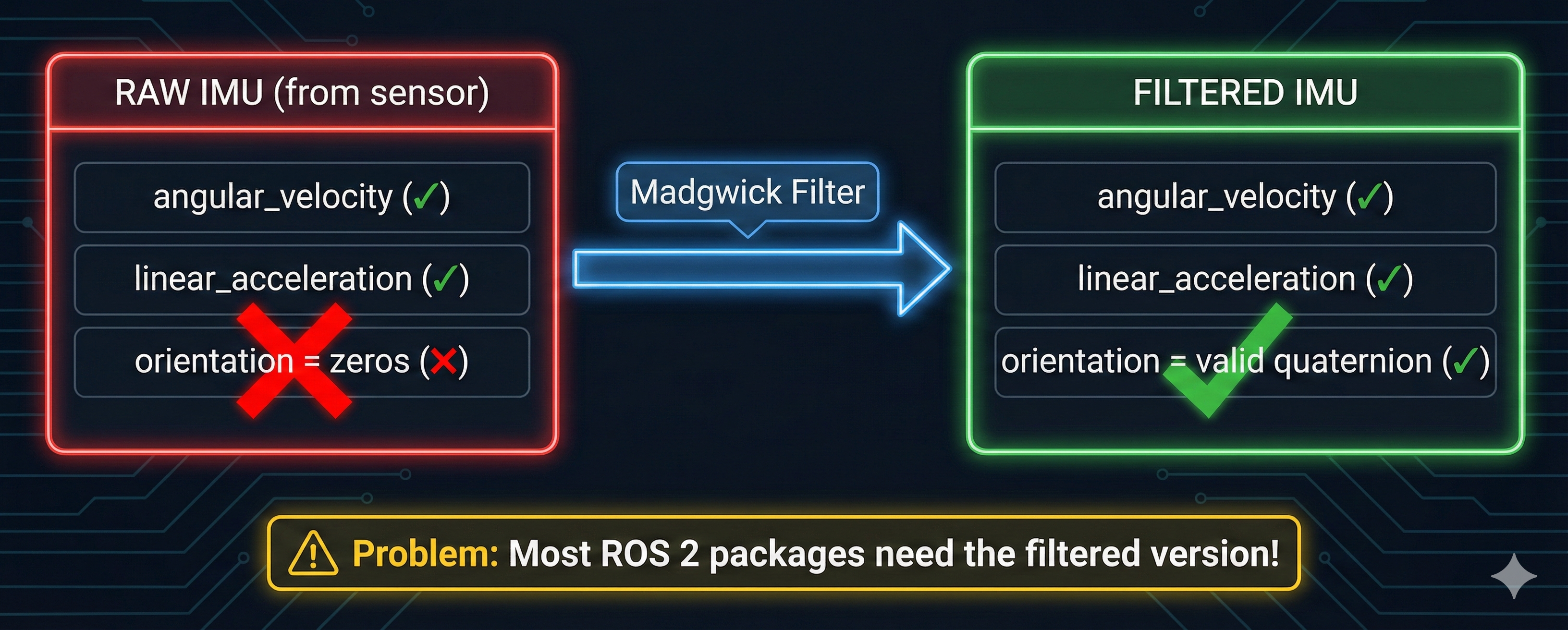
The RealSense driver publishes raw sensor readings: - ✅ angular_velocity - How fast we’re rotating (rad/s) - ✅ linear_acceleration - Forces on the sensor (m/s²) - ❌ orientation - All zeros!
The orientation_covariance[0] = -1 tells ROS 2: “orientation field is not provided”
Why This Matters
Many ROS 2 packages (like robot_localization, Nav2) expect IMU messages with valid orientation. They’ll fail or behave incorrectly with zeros!
┌─────────────────────────────────────────────────────────────────────────┐
│                     RAW IMU vs FILTERED IMU                             │
│                                                                         │
│    RAW (from sensor)              FILTERED (after processing)          │
│    ┌─────────────────┐            ┌─────────────────┐                  │
│    │ angular_velocity│──────────► │ angular_velocity│                  │
│    │ linear_accel    │  Filter    │ linear_accel    │                  │
│    │ orientation: 0  │  (Madgwick)│ orientation: ✓  │                  │
│    └─────────────────┘            └─────────────────┘                  │
│                                                                         │
│    Problem: Most ROS 2 packages need the filtered version!             │
└─────────────────────────────────────────────────────────────────────────┘
Eureka Moment #1
Accelerometer: Measures force (including gravity) → Need to integrate for velocity Gyroscope: Measures rotation rate → Need to integrate for orientation
A filter (like Madgwick) combines both to compute orientation. This is Exercise 2!
Experiment 2: Running the Madgwick Filter
What You’ll Learn
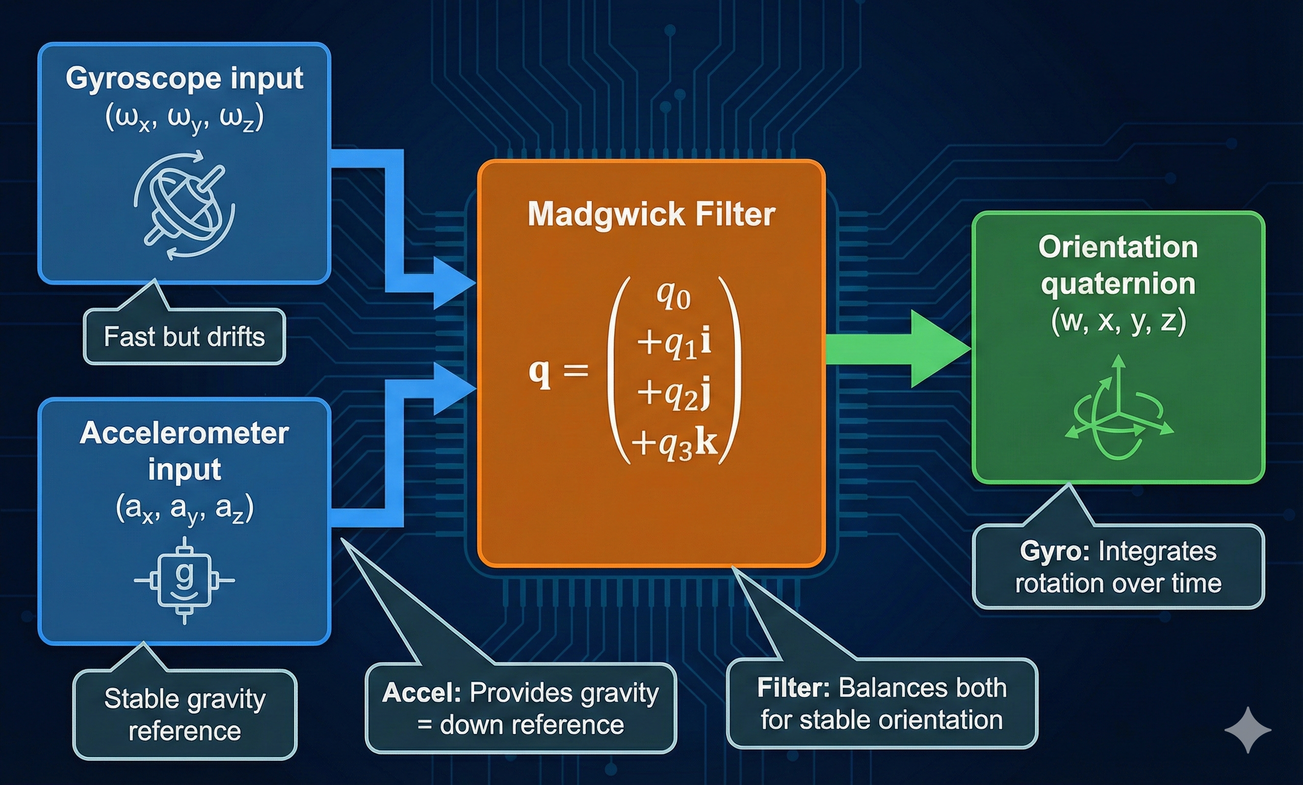
The Madgwick filter is a popular AHRS (Attitude and Heading Reference System) algorithm that computes orientation from raw IMU data.
Install and Run
# The filter is pre-installed in workshop4-imu container
# Terminal 1: RealSense with IMU
ros2 launch realsense2_camera rs_launch.py \
    enable_gyro:=true enable_accel:=true unite_imu_method:=2

# Terminal 2: Run Madgwick filter
ros2 run imu_filter_madgwick imu_filter_madgwick_node --ros-args \
    -r imu/data_raw:=/camera/camera/imu \
    -p use_mag:=false \
    -p publish_tf:=true \
    -p world_frame:=enu
Check the Filtered Output
# Now check the filtered IMU topic
ros2 topic echo /imu/data --field orientation
Now we see real orientation! Actual output from our test:
header:
  stamp:
    sec: 1765940920
    nanosec: 373782272
  frame_id: camera_imu_optical_frame
orientation:
  x: -0.5715487262389173    # ← Real values!
  y: 0.557508732210737
  z: -0.4266440447846019
  w: 0.42484223671061966    # ← Valid quaternion!
orientation_covariance:
- 0.0    # ← No longer -1! Filter provides orientation
# ...
Before Madgwick: orientation = (0, 0, 0, 0) ❌ After Madgwick: orientation = (-0.57, 0.56, -0.43, 0.42) ✅
Visualize in RViz2
rviz2
# Add displays:
# - TF (to see the imu frame)
# - Axes (to visualize orientation)
# Set fixed frame to: camera_link
The Filter in Action
┌─────────────────────────────────────────────────────────────────────────┐
│                    MADGWICK FILTER INTERNALS                            │
│                                                                         │
│    Gyroscope (ω)                                                       │
│    ┌───────────┐                                                       │
│    │ ωx, ωy, ωz│─────┐                                                 │
│    └───────────┘     │      ┌──────────────────┐                       │
│                      ├─────►│                  │     ┌──────────────┐  │
│    Accelerometer (a) │      │ Madgwick Filter  │────►│ Orientation  │  │
│    ┌───────────┐     │      │ (quaternion math)│     │ (q: w,x,y,z) │  │
│    │ ax, ay, az│─────┘      └──────────────────┘     └──────────────┘  │
│    └───────────┘                                                       │
│                                                                         │
│    Key insight: Accelerometer provides gravity reference (down)        │
│                 Gyroscope integrates rotation over time                │
│                 Filter balances both for stable orientation            │
└─────────────────────────────────────────────────────────────────────────┘
Eureka Moment #2
- Before Madgwick: orientation = (0, 0, 0, 0)
- After Madgwick: orientation = valid quaternion
The filter uses: 1. Gyroscope - integrates to get rotation 2. Accelerometer - uses gravity as “down” reference 3. Sensor fusion - balances fast gyro with stable accel
But there’s still a problem… (see Experiment 3!)
Experiment 3: Yaw Drift Without Magnetometer
The Test
# Terminal 1: RealSense + Madgwick (same as above)
# Terminal 2: Watch RPY (Roll-Pitch-Yaw)
ros2 topic echo /imu/rpy/filtered
Procedure
- Note the starting yaw value
- Slowly rotate the camera 360° horizontally
- Return to the exact starting position
- Check yaw again
Actual Console Output - Yaw Drift Test
We monitored Roll-Pitch-Yaw while keeping the camera completely stationary:
Monitoring YAW DRIFT for 10 seconds...
Keep camera STATIONARY to see drift!
Time Roll Pitch Yaw Yaw Drift
-------------------------------------------------------
0.0s -106.13 -0.81 -75.83 +0.0000
0.5s -106.12 -0.79 -75.78 +0.0454
1.0s -106.10 -0.78 -75.75 +0.0828
1.5s -106.17 -0.78 -75.71 +0.1185
2.0s -106.10 -0.80 -75.67 +0.1559
3.0s -106.07 -0.77 -75.61 +0.2203
4.0s -106.12 -0.76 -75.53 +0.3014
5.0s -106.15 -0.76 -75.44 +0.3847
6.0s -106.09 -0.77 -75.36 +0.4654
7.0s -106.12 -0.79 -75.28 +0.5497
8.0s -106.12 -0.82 -75.20 +0.6298
9.0s -106.13 -0.80 -75.13 +0.7012
10.0s -106.12 -0.75 -75.06 +0.7723
-------------------------------------------------------
STATIONARY YAW DRIFT: +0.8171 degrees over 10 seconds
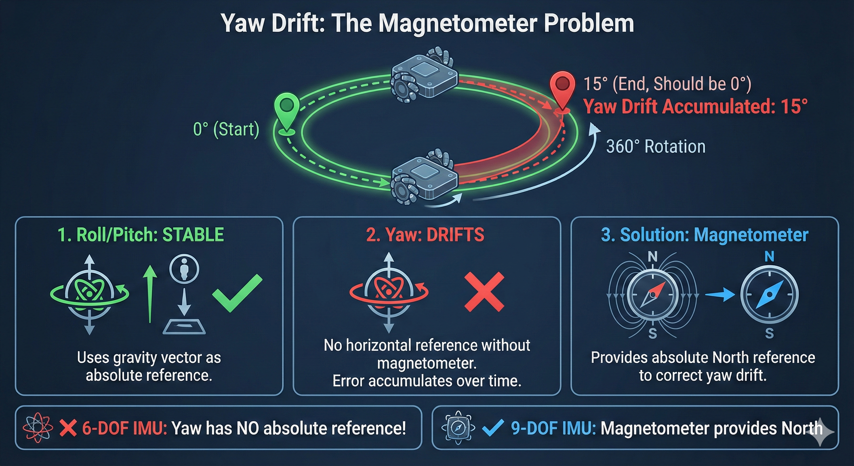
DRIFT RATE: +4.6712 degrees/minuteKey observations: - Roll: Stable at -106° (camera is tilted on its side) ✅ - Pitch: Stable at -0.8° ✅ - Yaw: Drifting from -75.83° → -75.06° even while stationary! ❌
At this rate: ~4.7°/minute = 280° drift per hour!
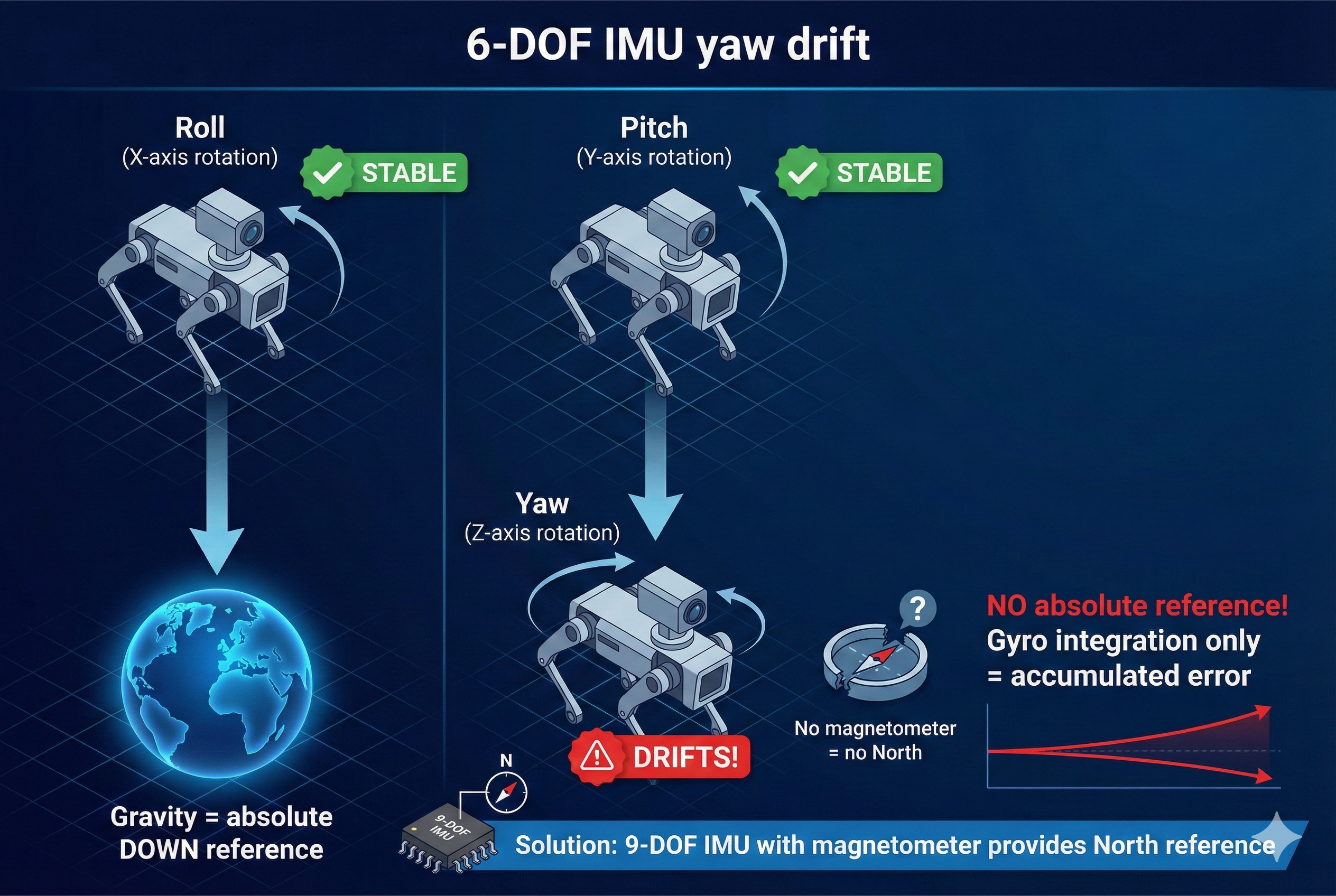
Roll and Pitch are stable because gravity provides an absolute reference (accelerometer knows which way is down).
Yaw has NO absolute reference! The D435i has no magnetometer to tell which way is north.
- Every rotation accumulates small errors
- Over time, yaw drifts unboundedly
- 360° rotation might report 370°, 350°, or worse!
Why This Happens
┌─────────────────────────────────────────────────────────────────────────┐
│                    YAW DRIFT PROBLEM (6-DOF IMU)                        │
│                                                                         │
│    Roll (rotation around X):                                           │
│    ┌─────────┐     Gravity provides                                    │
│    │ Stable! │ ◄── absolute "down" reference                           │
│    └─────────┘                                                         │
│                                                                         │
│    Pitch (rotation around Y):                                          │
│    ┌─────────┐     Gravity provides                                    │
│    │ Stable! │ ◄── absolute "down" reference                           │
│    └─────────┘                                                         │
│                                                                         │
│    Yaw (rotation around Z - vertical):                                 │
│    ┌─────────┐     NO absolute reference!                              │
│    │ DRIFTS! │ ◄── Gyro integration only = accumulated error           │
│    └─────────┘                                                         │
│                                                                         │
│    Solution: Magnetometer (9-DOF) provides "north" reference           │
│              → yDx.M offers 9/10-DOF configurations!                   │
└─────────────────────────────────────────────────────────────────────────┘
Eureka Moment #3
| IMU Type | Sensors | Yaw Reference | Drift |
|---|---|---|---|
| 6-DOF (D435i) | Accel + Gyro | None! | Unbounded |
| 9-DOF (with mag) | Accel + Gyro + Mag | Magnetic North | Bounded |
The yDx.M module from Yaanendriya offers 9/10-DOF configurations with magnetometer - solving this exact problem!
Experiment 4: Dead-Reckoning Disaster
The Ultimate IMU Failure
What if we try to track position by integrating acceleration? This is called “dead-reckoning.”
The Math (In Theory)
Position = ∫∫ Acceleration dt²

1. Measure acceleration (a)
2. Integrate to get velocity: v = ∫ a dt
3. Integrate again to get position: p = ∫ v dt
The Reality
# We'll use robot_localization to fuse IMU → position
# Create a minimal EKF config that uses ONLY IMU

cat > /tmp/imu_only_ekf.yaml << 'EOF'
ekf_filter_node:
  ros__parameters:
    frequency: 50.0
    sensor_timeout: 0.1
    two_d_mode: false

    map_frame: map
    odom_frame: odom
    base_link_frame: base_link
    world_frame: odom

    # IMU only - fusing acceleration to get position
    imu0: /imu/data
    imu0_config: [false, false, false,   # Don't use position (IMU has none)
                  true,  true,  true,    # Use orientation (roll, pitch, yaw)
                  false, false, false,   # Don't use velocity directly
                  true,  true,  true,    # Use angular velocity
                  true,  true,  true]    # Use linear acceleration
    imu0_differential: false
    imu0_remove_gravitational_acceleration: true
EOF

# Run EKF
ros2 run robot_localization ekf_node --ros-args \
    --params-file /tmp/imu_only_ekf.yaml
Watch Position Drift
# In another terminal - watch the odometry output
ros2 topic echo /odometry/filtered --field pose.pose.position
Actual Console Output - The Disaster Unfolds
We integrated acceleration to compute position with the camera sitting perfectly still:
DEAD RECKONING - Integrating acceleration to get position
Camera should be STATIONARY - watch position drift!
Time Position (m) Velocity (m/s)
X Y Z Vx Vy Vz
------------------------------------------------------------------------
1.0s 0.068 -4.707 -1.345 0.135 -9.367 -2.676
2.0s 0.270 -18.783 -5.366 0.268 -18.736 -5.352
3.0s 0.606 -42.226 -12.064 0.403 -28.100 -8.029
5.0s 1.681 -117.200 -33.484 0.672 -46.834 -13.381
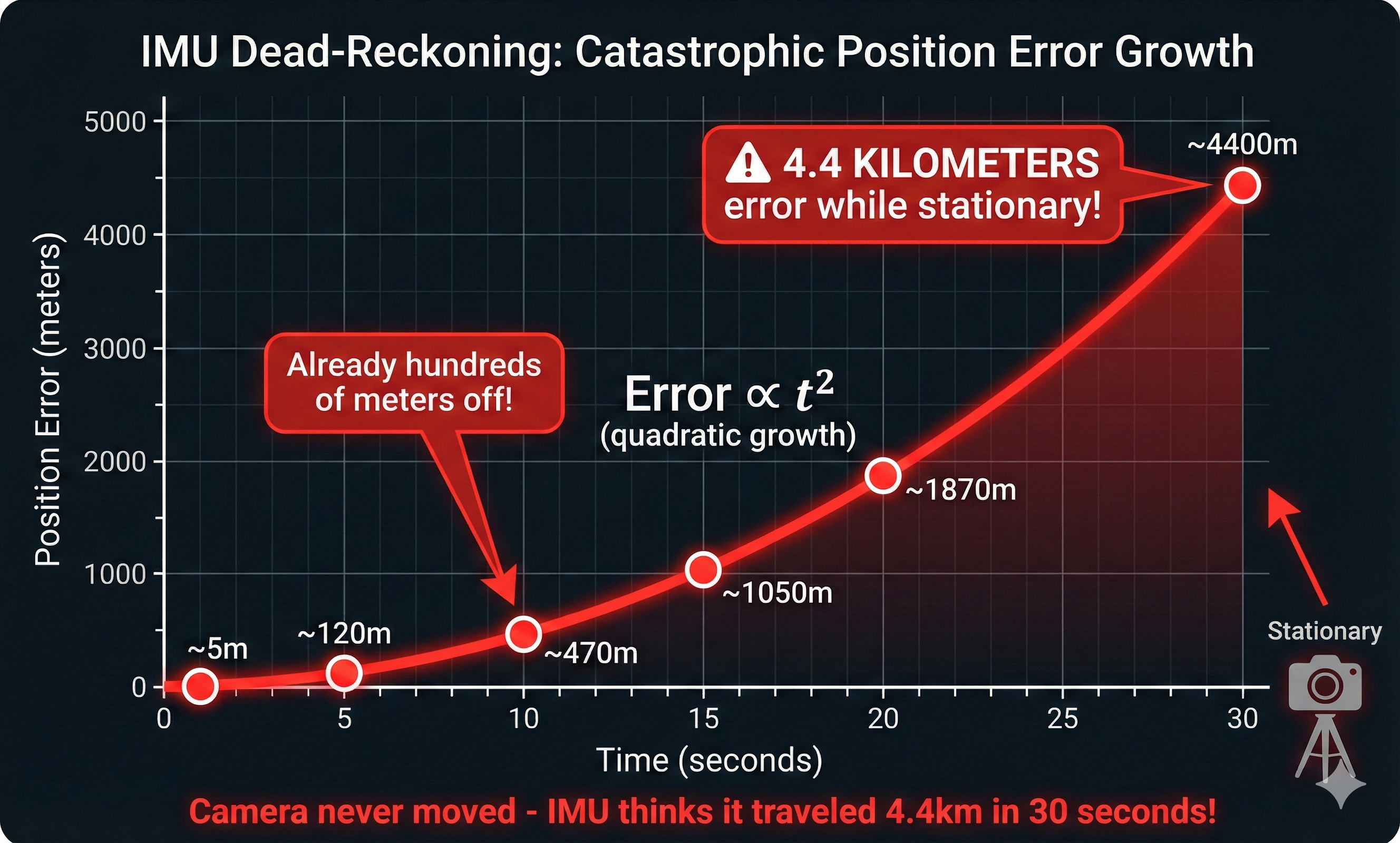
10.0s 6.733 -468.597 -133.859 1.348 -93.675 -26.757
15.0s 15.157 -1054.147 -301.123 2.021 -140.508 -40.136
20.0s 26.887 -1869.728 -534.111 2.692 -187.135 -53.459
25.0s 41.974 -2917.539 -833.429 3.366 -233.772 -66.778
30.0s 60.420 -4198.513 -1199.342 4.039 -280.437 -80.107
------------------------------------------------------------------------
FINAL POSITION ERROR: 4385.88 meters (should be 0!)
Camera was STATIONARY but IMU thinks it moved 4385.9 meters!The camera never moved, yet the IMU computed: - Position drift: 4.4 KILOMETERS in 30 seconds! - Velocity error: 280 m/s (faster than a race car!) - This is completely unusable for navigation!
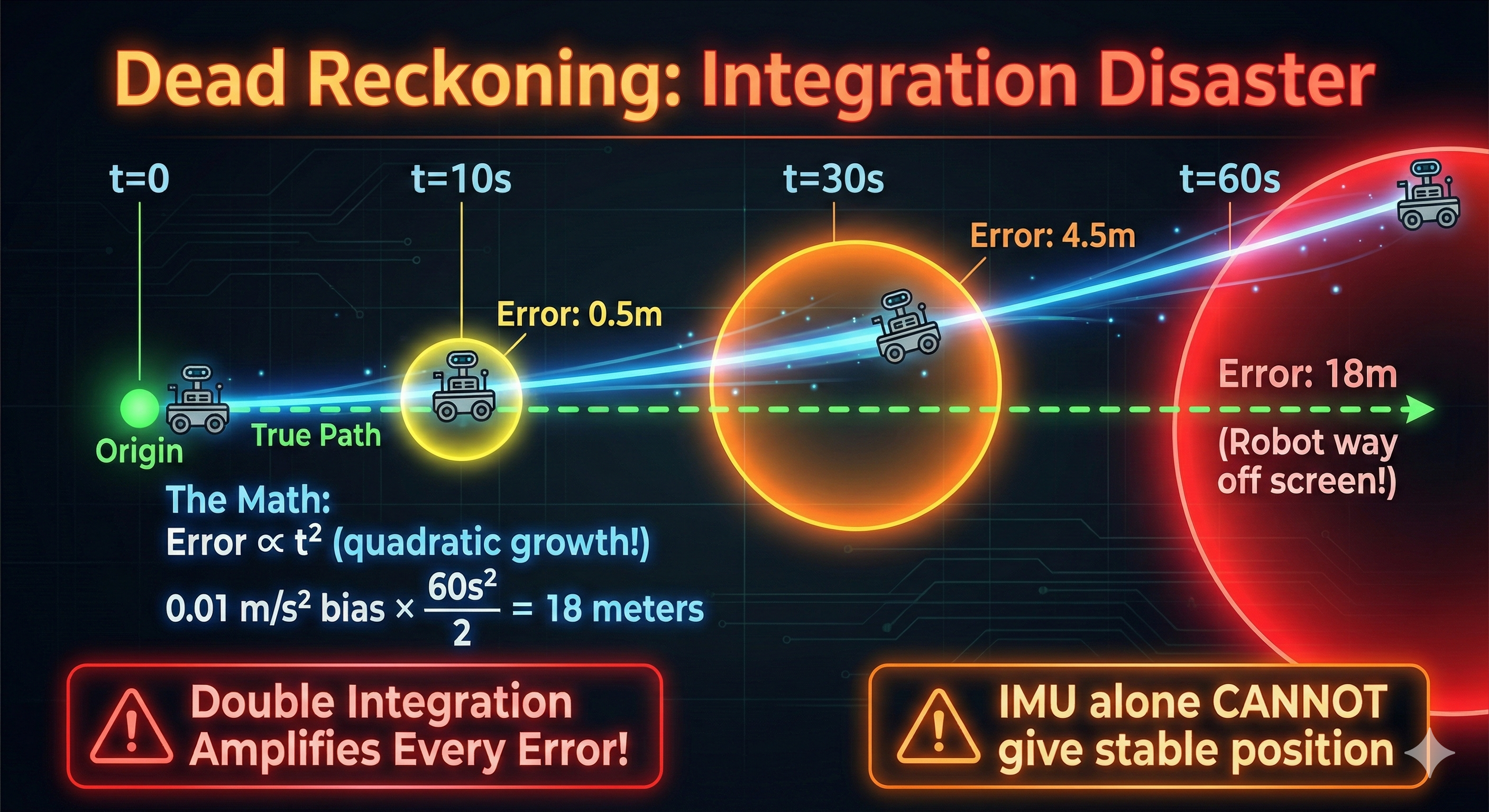
The problem: noise integrates!
- Accelerometer has tiny bias: 0.01 m/s²
- After 1 second: velocity error = 0.01 m/s
- After 10 seconds: velocity error = 0.1 m/s
- Position error grows quadratically with time!
Error ∝ t² (quadratic growth!)After 60 seconds with 0.01 m/s² bias: - Velocity error: 0.6 m/s - Position error: ~18 meters! 🤯
Eureka Moment #4
Why IMU can’t give position: 1. Tiny accelerometer bias → velocity drift 2. Velocity drift → position drift (squared!) 3. Within seconds: meters of error 4. No way to correct without external reference
This is why we need sensor fusion (Part 3) - visual odometry provides position corrections!
Experiment 5: The Calibration Reality
Uncalibrated vs Calibrated
The D435i IMU is NOT factory calibrated. Let’s see the difference!
Measure Stationary Noise
# Place camera on flat, stable surface
# Record 10 seconds of IMU data

ros2 bag record /camera/camera/imu -o imu_stationary --duration 10

# Analyze the variance
ros2 bag play imu_stationary &
ros2 topic echo /camera/camera/imu --field linear_acceleration | head -100
Actual Console Output - Bias Measurement
We measured 1000 samples (~5 seconds) from a stationary D435i:
CALIBRATION TEST - Measuring IMU bias and noise
Camera should be STATIONARY on a flat surface
Collecting 1000 samples (~5 seconds at 200Hz)...

============================================================
ACCELEROMETER ANALYSIS (should be [0, 0, 9.81] if flat)
============================================================

Axis     Mean (m/s2)    Std Dev    Bias from expected
------------------------------------------------------------
X         +0.1427      0.0075      +0.1427 (expect 0)
Y         -9.4008      0.0075      -9.4008 (expect 0)
Z         -2.5576      0.0082      -12.3676 (expect 9.81)

Gravity magnitude: 9.7436 m/s2 (expected: 9.81)
Note: Camera is tilted, so gravity is distributed across axes

============================================================
GYROSCOPE ANALYSIS (should be [0, 0, 0] when stationary)
============================================================

Axis     Mean (rad/s)   Std Dev        Bias
------------------------------------------------------------
X       -0.003032    0.002499    -0.003032 rad/s
Y       -0.001384    0.002205    -0.001384 rad/s
Z       -0.000463    0.001468    -0.000463 rad/s

Gyro bias in deg/s: X=-0.1737  Y=-0.0793  Z=-0.0265

IMPACT: 0.1737 deg/s bias = 10.42 deg drift per minute!
Key findings: - Gyro X-axis bias: -0.17°/s → causes 10.4° drift per minute! - Gravity magnitude: 9.74 m/s² (vs expected 9.81) - 0.7% error - Std dev: ~0.002 rad/s - shows sensor noise level
Eureka Moment #5
| Measurement | Value | Impact |
|---|---|---|
| Gyro X bias | -0.17°/s | 10.4°/min drift |
| Gyro Y bias | -0.08°/s | 4.8°/min drift |
| Gyro Z bias | -0.03°/s | 1.6°/min drift |
| Gravity error | 0.7% | Affects tilt calculation |
This explains Experiment 3! The ~4.7°/min yaw drift we measured earlier comes directly from these gyro biases being integrated over time.
yDx.M is factory calibrated - eliminating this source of error!
Experiment 6: Coordinate Frame Confusion
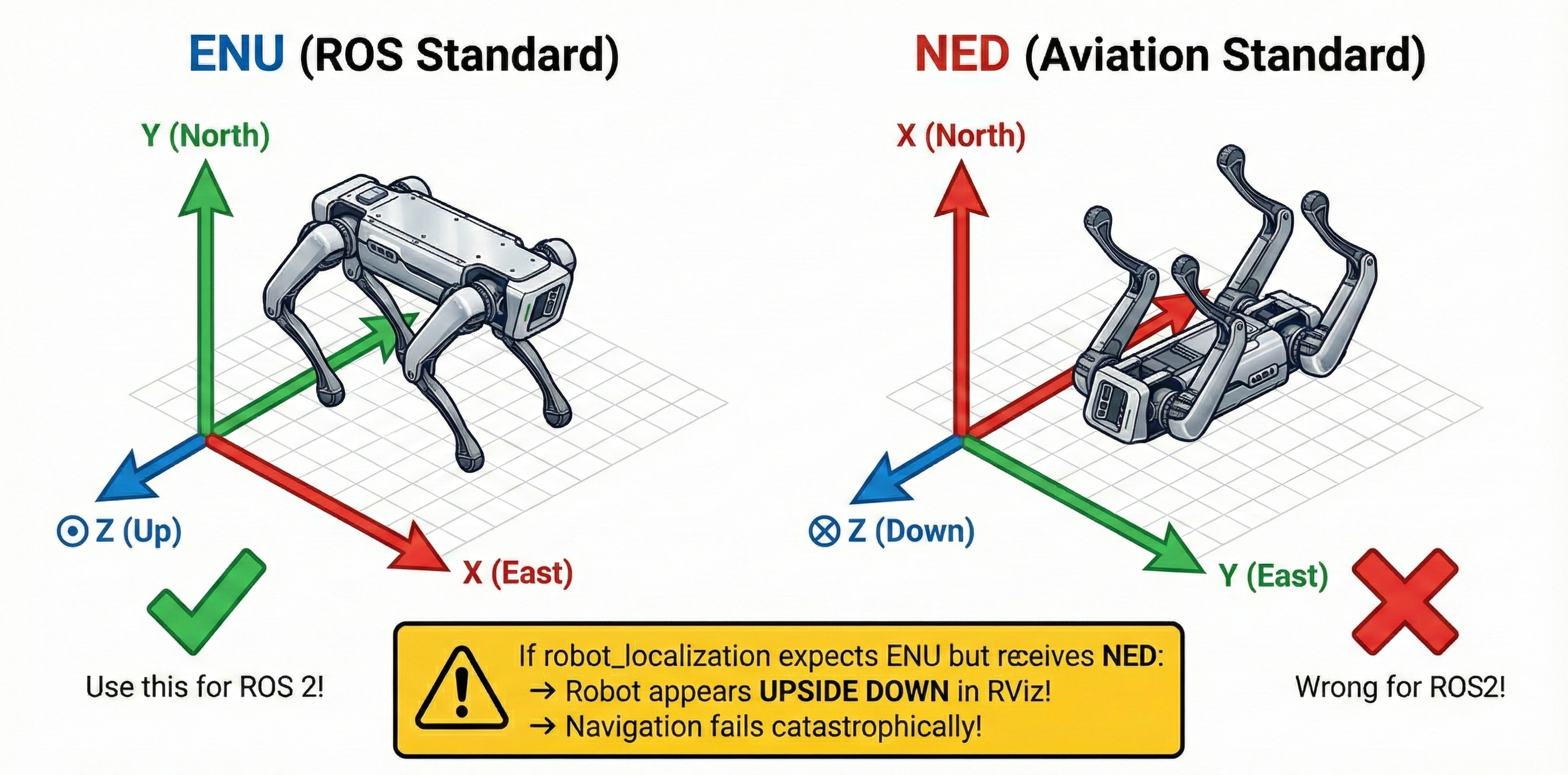
ENU vs NED: The Silent Disaster
ROS 2 uses ENU (East-North-Up) frame convention. Aviation uses NED (North-East-Down). Mixing them causes chaos!
The Test
# Check what frame the Madgwick filter outputs
ros2 run imu_filter_madgwick imu_filter_madgwick_node --ros-args \
    -r imu/data_raw:=/camera/camera/imu \
    -p world_frame:=enu   # ROS standard

# Compare with NED (wrong for ROS!)
ros2 run imu_filter_madgwick imu_filter_madgwick_node --ros-args \
    -r imu/data_raw:=/camera/camera/imu \
    -p world_frame:=ned   # Aviation standard
What Happens with Wrong Frame
┌─────────────────────────────────────────────────────────────────────────┐
│                    COORDINATE FRAME MISMATCH                            │
│                                                                         │
│    ENU (ROS Standard)              NED (Aviation Standard)             │
│    ┌─────────────────┐             ┌─────────────────┐                 │
│    │     Y (North)   │             │     X (North)   │                 │
│    │        ↑        │             │        ↑        │                 │
│    │        │        │             │        │        │                 │
│    │   ─────┼────► X │             │   ─────┼────► Y │                 │
│    │    (East)       │             │    (East)       │                 │
│    │    Z: Up ⊙      │             │    Z: Down ⊗    │                 │
│    └─────────────────┘             └─────────────────┘                 │
│                                                                         │
│    If robot_localization expects ENU but receives NED:                 │
│    → Robot appears UPSIDE DOWN in RViz!                                │
│    → Position estimates are inverted!                                  │
│    → Navigation fails catastrophically!                                │
└─────────────────────────────────────────────────────────────────────────┘
Eureka Moment #6
| Package | Expected Frame | Standard |
|---|---|---|
robot_localization |
ENU | REP-103 |
Nav2 |
ENU | REP-103 |
| Most IMU drivers | Configurable | Check docs! |
| Aviation software | NED | Not ROS! |
Always verify:
ros2 param get /imu_filter_madgwick world_frameActual output from our test:
String value is: enu✅ Our Madgwick filter is correctly configured for ROS 2!
Experiment 7: Understanding Covariance
Why Covariance Matrices Matter
Every sensor_msgs/Imu message has three 3×3 covariance matrices. These tell filters how much to trust each measurement.
Check the Covariances
ros2 topic echo /camera/camera/imu --once | grep -A10 "covariance"Actual output from our D435i:
orientation_covariance:
- -1.0          # ← -1 means "NOT PROVIDED"
- 0.0
- 0.0
# ... (rest zeros)

angular_velocity_covariance:
- 0.01          # ← Diagonal: variance of X rotation
- 0.0
- 0.0
- 0.0
- 0.01          # ← Diagonal: variance of Y rotation
- 0.0
- 0.0
- 0.0
- 0.01          # ← Diagonal: variance of Z rotation

linear_acceleration_covariance:
- 0.01          # Same pattern: 0.01 on diagonal
- 0.0
# ...
What These Values Mean
Covariance Matrix (3x3, stored as 9 elements row-major):
┌                   ┐
│ σxx  σxy  σxz     │   σxx = variance of x measurement
│ σyx  σyy  σyz     │   σyy = variance of y measurement
│ σzx  σzy  σzz     │   σzz = variance of z measurement
└                   ┘   Off-diagonal = correlation

Small values (0.001) = High confidence, trust this data
Large values (1.0)   = Low confidence, don't trust as much
The Impact on Filtering
# With proper covariances - EKF works well
imu0_config: [false, false, false,
              true,  true,  true,    # orientation
              false, false, false,
              true,  true,  true,    # angular velocity
              true,  true,  true]    # acceleration

# Wrong covariances cause:
# - Filter divergence (estimates explode)
# - Sluggish response (overestimated covariance)
# - Overconfident (underestimated covariance → crashes)
Eureka Moment #7
| Covariance | Effect on Filter |
|---|---|
| Too small | Filter trusts noisy data → oscillation |
| Too large | Filter ignores good data → slow response |
| Just right | Optimal sensor fusion |
yDx.M advantage: Yaanendriya likely provides calibrated covariance values tuned for their hardware!
Summary: 7 Problems With IMU Alone
┌─────────────────────────────────────────────────────────────────────────┐
│              PART 1 SUMMARY: WHY IMU ALONE FAILS                        │
│                                                                         │
│   Problem #1: Raw IMU has no orientation (zeros!)                      │
│   ───────────────────────────────────────────────                      │
│   Solution: Use filter (Madgwick, complementary)                       │
│                                                                         │
│   Problem #2: Yaw drifts without magnetometer                          │
│   ───────────────────────────────────────────────                      │
│   Solution: 9-DOF IMU with magnetometer (yDx.M)                        │
│                                                                         │
│   Problem #3: Position drift from integration                          │
│   ───────────────────────────────────────────────                      │
│   Solution: Sensor fusion with visual odometry (Part 3!)               │
│                                                                         │
│   Problem #4: Uncalibrated sensors have bias                           │
│   ───────────────────────────────────────────────                      │
│   Solution: Run calibration OR use factory-calibrated IMU              │
│                                                                         │
│   Problem #5: Frame convention mismatches                              │
│   ───────────────────────────────────────────────                      │
│   Solution: Ensure ENU frame throughout ROS 2 pipeline                 │
│                                                                         │
│   Problem #6: Wrong covariances = bad fusion                           │
│   ───────────────────────────────────────────────                      │
│   Solution: Tune covariances or use manufacturer values                │
│                                                                         │
│   Problem #7: Single point of failure                                  │
│   ───────────────────────────────────────────────                      │
│   Solution: Distributed sensing (yDx.M network feature!)               │
│                                                                         │
└─────────────────────────────────────────────────────────────────────────┘
What’s Next: The Cliffhanger
We’ve seen that IMU alone has serious limitations: - No absolute yaw reference - Position drifts in seconds - Needs calibration and proper filtering
But wait - we have a camera too!
In Part 2, we’ll try using vision-only approaches: - Visual odometry with RTAB-Map - What happens when we shake the camera? - What happens with textureless walls?
Spoiler: Vision has its own set of problems… but they’re different problems. This sets up Part 3 where we’ll combine both for robust Visual-Inertial Odometry (VIO)!
Preparation Checklist
Before Workshop 4, make sure you can:
About Yaanendriya’s yDx.M
The workshop will feature Yaanendriya’s yDx.M module - here’s how it addresses today’s problems:
| D435i Problem | yDx.M Solution |
|---|---|
| No orientation from raw IMU | Built-in AHRS |
| Yaw drift (no magnetometer) | 9/10-DOF with magnetometer |
| Manual calibration required | Factory calibrated |
| Single sensor failure | Distributed sensor network |
| Covariance tuning | Pre-tuned for hardware |
We’re building understanding of the problems - the workshop will show us the professional solutions!