Creating Go2W USD: The Right Tool for the Job
A Journey from Manual pxr API to Isaac Lab’s UrdfConverter
This tutorial is guided by Dr. Nova Brooks, your AI mentor for robotics and simulation.
The Journey Begins
Rajesh: Dr. Nova, I’ve been working with the Newton physics engine and ran into a frustrating problem. When I load my Go2W robot from URDF, it creates 35 shapes instead of the expected 17. The simulation is loading both visual AND collision geometry!
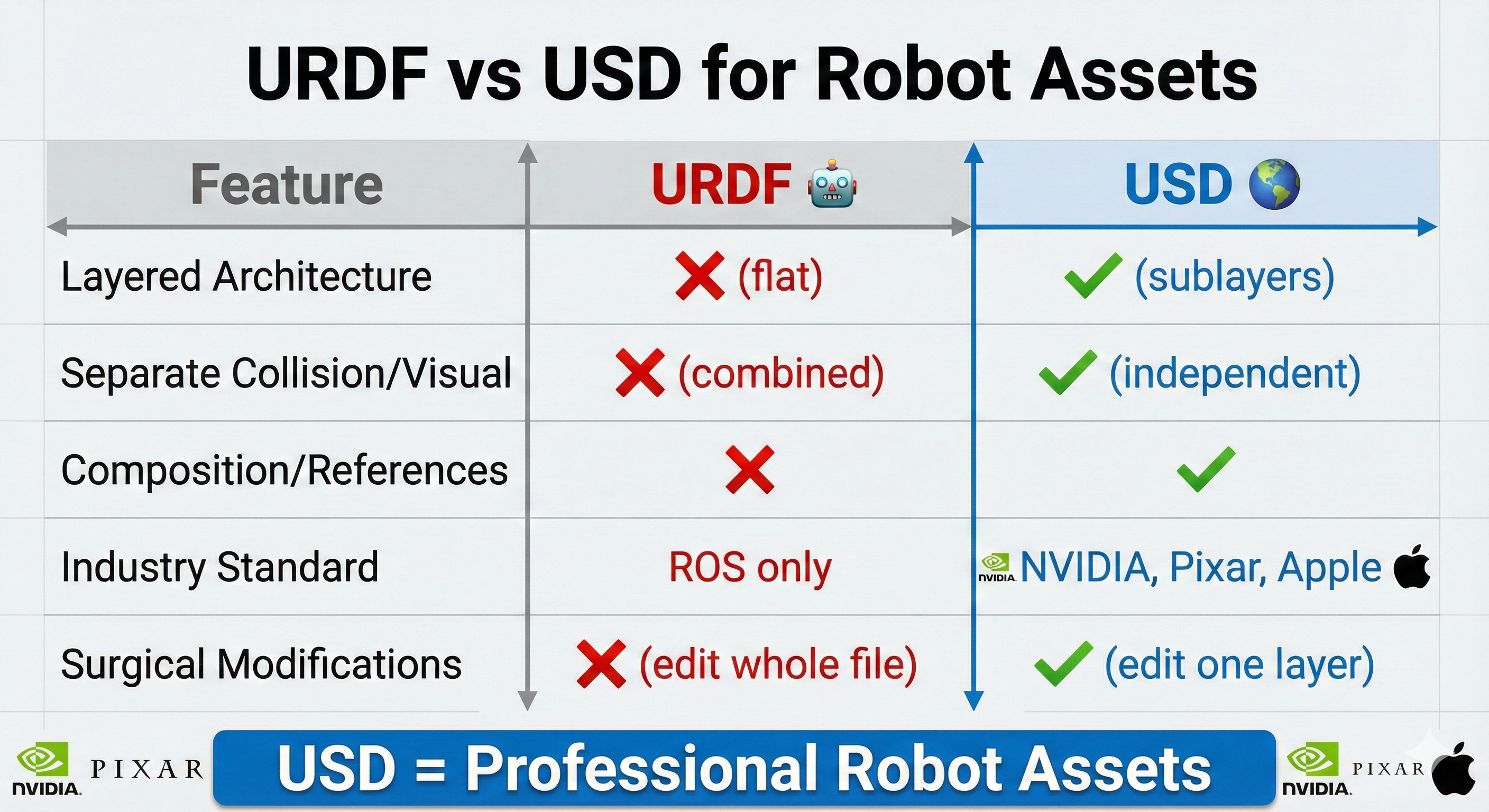
Dr. Nova Brooks: Ah, the classic URDF double-counting problem! This is exactly why NVIDIA uses USD (Universal Scene Description) for their professional robot assets. But here’s the thing - let me save you from a path I’ve seen many engineers take…
When Newton loads URDF files, it processes both visual and collision geometry as physics shapes. For a robot with 17 bodies, this creates 35+ shapes, causing incorrect collision detection and heavier simulation load.
The Hard Way vs. The Smart Way
Rajesh: So I need to convert my URDF to USD. Let me start writing a script with the pxr API to manually create USD layers…
Dr. Nova Brooks: holds up hand Stop right there! I need to tell you something important. When I first started with Isaac Sim, I spent weeks writing manual USD manipulation code - modifying collision geometry, converting joints, updating visual references. It was educational, but…
Rajesh: But?
Dr. Nova Brooks: Isaac Lab has a tool that does ALL of that in a single command. Let me show you what I learned the hard way:
The Lesson Learned
“When working with robot models in Isaac Sim: Start with the official URDF from the manufacturer and use Isaac Lab’s converter. Don’t try to manually create USD files or fix mesh positioning with custom scripts. The official toolchain handles everything correctly.”
The Simple Way: UrdfConverter
Dr. Nova Brooks: Here’s the one-liner that replaces 500+ lines of manual pxr API code:
Command Line (That’s It!)
./isaaclab.sh -p scripts/tools/convert_urdf.py \
    <path/to/robot.urdf> \
    <output/path/robot.usd> \
    --headless
Python Code (With Critical Settings)
convert_go2w_official.py
"""
Convert Go2W URDF to USD using Isaac Lab's UrdfConverter.

This script demonstrates the recommended approach for converting robot URDFs
to USD format for use with Isaac Sim and Newton physics.

Official Documentation:
    https://isaac-sim.github.io/IsaacLab/main/source/api/lab/isaaclab.sim.converters.html

Run with:
    ./isaaclab.sh -p convert_go2w_official.py
"""

from isaaclab.sim.converters import UrdfConverter, UrdfConverterCfg

# =============================================================================
# URDF CONVERTER CONFIGURATION
# Full parameter reference: UrdfConverterCfg in Isaac Lab docs
# =============================================================================

cfg = UrdfConverterCfg(
    # -------------------------------------------------------------------------
    # Input/Output Paths
    # -------------------------------------------------------------------------
    asset_path="/path/to/go2w_description.urdf",  # Source URDF file
    usd_dir="/path/to/output/",                   # Output directory
    usd_file_name="go2w.usd",                     # Output filename

    # -------------------------------------------------------------------------
    # MOBILE ROBOT SETTINGS
    # These are critical for wheeled/legged robots that need to move freely
    # -------------------------------------------------------------------------

    # fix_base: Should the robot's base link be welded to the world?
    #   False = Mobile robot (Go2W can drive around)
    #   True  = Fixed manipulator (robot arm bolted to table)
    fix_base=False,

    # merge_fixed_joints: Consolidate zero-mass "dummy" links?
    #   True  = Merge sensor mounts, collision helpers into parent links
    #   False = Keep all links separate (may cause physics instability)
    merge_fixed_joints=True,

    # collision_from_visuals: Generate collision geometry from visual meshes?
    #   False = Use URDF's <collision> tags (fast primitives: boxes, cylinders)
    #   True  = Use visual meshes for collision (slow, usually unnecessary)
    collision_from_visuals=False,

    # link_density: Override mass calculation with density estimation?
    #   0.0 = Trust URDF masses (use <inertial> tags as specified)
    #   >0  = Estimate mass from geometry volume × density (ignores URDF)
    link_density=0.0,

    # make_instanceable: Enable GPU instancing for parallel environments?
    #   True  = Share mesh data across 4096+ robot instances (saves VRAM)
    #   False = Each robot has its own mesh copy
    make_instanceable=True,

    # -------------------------------------------------------------------------
    # RL TRAINING SETTINGS
    # These ensure the policy has direct control over joint torques
    # -------------------------------------------------------------------------

    joint_drive=UrdfConverterCfg.JointDriveCfg(
        # drive_type: How are joint commands interpreted?
        #   "force"    = Direct torque control (τ = command)
        #   "position" = PD position tracking (adds control layer)
        drive_type="force",

        # target_type: What does the drive track?
        #   "none"     = No tracking, pure torque mode
        #   "position" = Track position target
        #   "velocity" = Track velocity target
        target_type="none",

        # PD gains: Only relevant if drive_type="position"
        #   For RL, we set both to 0 so policy has full control
        gains=UrdfConverterCfg.JointDriveCfg.PDGainsCfg(
            stiffness=0.0,  # Position gain (Kp) - set to 0 for torque mode
            damping=0.0,    # Velocity gain (Kd) - set to 0 for torque mode
        ),
    ),
)

# =============================================================================
# RUN CONVERSION
# =============================================================================

converter = UrdfConverter(cfg)
print(f"✓ Converted to: {converter.usd_path}")Rajesh: Wait… that’s it? All those pxr API calls I was about to write… mesh conversion, physics properties, joint setup…
Dr. Nova Brooks: All handled automatically. The converter:
- Converts meshes (DAE → USD)
- Transfers physics (mass, inertia, center of mass)
- Sets up joints correctly
- Separates collision and visual geometry
- Creates the layered USD structure
Understanding the Critical Settings
Rajesh: Those settings look important. Can you explain what each one does?
Dr. Nova Brooks: Absolutely! Getting these wrong is where most people run into trouble:
Mobile Robot Settings
| Setting | Value | Why It Matters |
|---|---|---|
fix_base |
False |
Mobile robot needs to move! True would weld it to ground |
merge_fixed_joints |
True |
Consolidates zero-mass sensor mounts automatically |
collision_from_visuals |
False |
Uses URDF’s collision geometry (fast primitives) |
link_density |
0.0 |
Uses actual URDF masses instead of estimating from geometry |
make_instanceable |
True |
Enables GPU instancing for 4096+ parallel environments |
RL Training Settings
| Setting | Value | Why It Matters |
|---|---|---|
drive_type |
"force" |
Direct torque control (what RL policies output) |
target_type |
"none" |
No built-in PD tracking - policy has full control |
stiffness |
0.0 |
No position tracking (pure velocity/torque mode) |
damping |
0.0 |
No velocity damping (policy controls everything) |
Common Mistakes to Avoid
Dr. Nova Brooks: Here are the mistakes I’ve seen - and made - when setting up robot USD:
| Wrong Setting | Problem |
|---|---|
fix_base=True |
Robot stuck to ground, can’t move! |
merge_fixed_joints=False |
Zero-mass bodies cause physics errors |
collision_from_visuals=True |
Uses mesh geometry (slow, inaccurate) |
drive_type="position" |
Forces PD control, breaks RL training |
link_density > 0 |
Overrides URDF masses with estimates |
The Dummy Link Issue
Rajesh: What about those sensor links with zero mass? I’ve seen warnings about them.
Dr. Nova Brooks: Great question! The Go2W URDF has several “dummy” links:
Zero-Mass Bodies (Handled Automatically)
The Go2 URDF contains intermediate collision links and sensor mounts:
*_calflower- Extra collision cylinders at 0.148m offset*_calflower1- Additional collision at 0.04m offsetimu,radar- Sensor mount bodies with mass=0.0
Solution: merge_fixed_joints=True consolidates these automatically!
Missing Visual References (Cosmetic Fix)
The Head_lower and Head_upper sensor mounts may reference visual geometry that doesn’t exist, causing warnings like:
Warning: Unable to find visual prim at path '/Head_lower/visuals'Fix: Add empty Xform placeholders in the USD for the missing visuals:
Head_lower/visuals  <- Empty Xform placeholder
Head_upper/visuals  <- Empty Xform placeholder
This is purely cosmetic - the sensors work fine without visual meshes, but the USD structure expects them.
Understanding USD Architecture
Rajesh: Even though the converter handles everything, I’d still like to understand what it creates.
Dr. Nova Brooks: Excellent attitude! Understanding the output helps with debugging. Here’s the layered structure the UrdfConverter creates:
go2w_official.usd                       # Main entry point
├── configuration/
│   ├── go2w_official_base.usd         # Visual geometry & meshes
│   ├── go2w_official_robot.usd        # Articulation & joints
│   ├── go2w_official_physics.usd      # Physics properties
│ └── go2w_official_sensor.usd # Sensors (IMU, radar)| Layer | Purpose | Contains |
|---|---|---|
*_base.usd |
Geometry | Mesh references, collider shapes, visual transforms |
*_physics.usd |
Physics | Mass properties, inertia tensors |
*_robot.usd |
Structure | Joint definitions, articulation hierarchy |
*_sensor.usd |
Sensors | IMU, radar, camera configurations |
This separation lets you modify physics without touching geometry, or swap visual meshes without affecting the physics simulation.
Wheel Specifications (For Reference)
Rajesh: What about the Go2W wheel specs? Are those preserved correctly?
Dr. Nova Brooks: The converter pulls these directly from the URDF. Here’s what the Go2W has:
Wheel Specifications from Go2W URDF
# Wheel parameters extracted from Go2W URDF
WHEEL_RADIUS = 0.085      # meters
WHEEL_LENGTH = 0.04       # meters (width)
WHEEL_MASS = 1.166        # kg (motor + wheel combined)
WHEEL_EFFORT_LIMIT = 23.7 # Nm (max torque)

# Wheel inertia (from URDF)
WHEEL_INERTIA = {
    "ixx": 0.0017,
    "iyy": 0.0028,  # Around rotation axis
    "izz": 0.0017
}
Verified Physics Properties
| Property | Value |
|---|---|
| Wheel Mass | 1.166 kg (0.646 motor + 0.520 wheel) |
| Wheel COM (Y) | ±0.06 m (left +, right -) |
| Wheel Inertia | (0.0017, 0.0028, 0.0017) |
| Collision Radius | 0.085 m |
| Collision Height | 0.04 m |
| Joint Type | Continuous (RevoluteJoint) |
| Joint Axis | Y |
The “Aha Moment” We Almost Missed
Rajesh: So if the converter does everything… what’s the educational value here?
Dr. Nova Brooks: Great question! Here’s the insight that’s still valuable - even when using the converter:
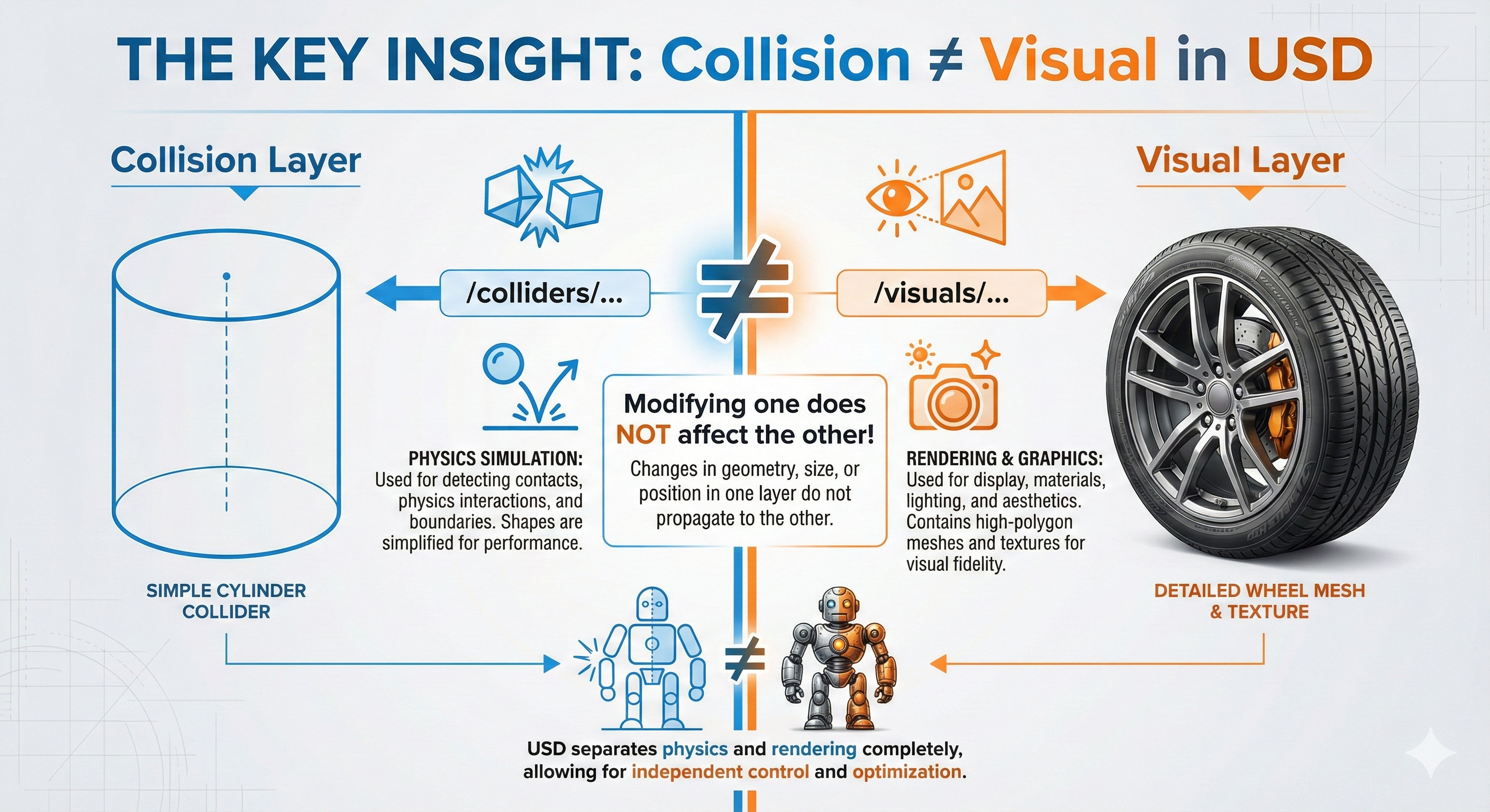
THE KEY INSIGHT: Collision ≠ Visual!
In USD, collision geometry and visual geometry are completely separate!
This means:
- You can have simple collision primitives (fast physics)
- With detailed visual meshes (pretty rendering)
- They’re independent and can be modified separately
The converter handles this automatically, but understanding it helps when debugging. If your robot “looks” wrong but physics is correct - check the visual layer!
The Result: Go2W USD Ready for Simulation
Rajesh: Let me run the conversion and see the result…
Dr. Nova Brooks: Here’s your Go2W loaded in the Newton physics viewer - wheels, collision geometry, and all physics properties correctly transferred from the URDF:
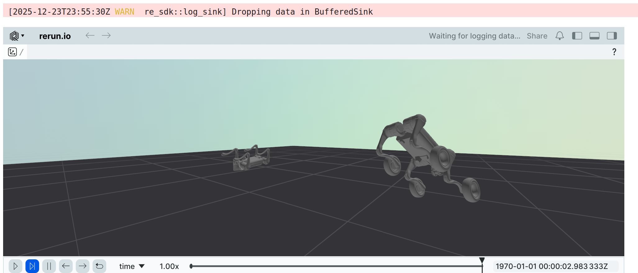
The UrdfConverter automatically handled:
- Wheel meshes - Converted from DAE to USD
- Collision cylinders - Proper radius (0.085m) and axis (Y)
- RevoluteJoints - Continuous rotation for wheels
- Physics properties - Mass, inertia, center of mass from URDF
- Layered USD structure - Separate base, physics, robot, and sensor layers
Key Learnings: What This Journey Taught Us
Dr. Nova Brooks: So Rajesh, what did we learn?
Rajesh: The most important lesson: use the right tool for the job! I was about to spend days writing manual USD manipulation code when a single converter call does everything.
Dr. Nova Brooks: Exactly. And here’s the full picture:
Key Takeaways
Use Isaac Lab’s UrdfConverter - It handles mesh conversion, physics transfer, joint setup, and layered USD structure automatically.
Get the settings right -
fix_base=Falsefor mobile robots,merge_fixed_joints=Trueto handle dummy links,drive_type="force"for RL training.Understand the output - Even when using tools, knowing USD’s layered architecture helps with debugging.
Collision ≠ Visual - They’re separate in USD. If something looks wrong but physics is right, check the visual layer.
Don’t reinvent the wheel - (Pun absolutely intended!) Start with manufacturer URDFs and official conversion tools.
Quick Reference
One-Liner Conversion
# From Isaac Lab root directory
./isaaclab.sh -p scripts/tools/convert_urdf.py \
    /path/to/go2w_description.urdf \
    /path/to/output/go2w.usd \
    --headless
Critical Settings Cheat Sheet
| Setting | Mobile Robot | Fixed Arm | Why |
|---|---|---|---|
fix_base |
False |
True |
Mobile = floating base |
merge_fixed_joints |
True |
True |
Removes zero-mass links |
collision_from_visuals |
False |
False |
Use URDF collision geometry |
link_density |
0.0 |
0.0 |
Trust URDF masses |
drive_type |
"force" |
"force" |
Direct torque for RL |
File Locations
| File | Path |
|---|---|
| Source URDF | /workspace/isaaclab/robot_lab/.../go2w_description/urdf/official_unitree/go2w_description_isaac.urdf |
| Output USD | /workspace/isaaclab/robot_lab/.../go2w_description/usd/go2w_official.usd |
| Conversion Script | /workspace/isaaclab/IsaacLab/tools/newton_tutorials/convert_go2w_official.py |
Quick Troubleshooting
| Symptom | Check This |
|---|---|
| Robot stuck to ground | fix_base=False? |
| Physics explosions | merge_fixed_joints=True? Zero-mass bodies? |
| Wrong mass/inertia | link_density=0.0? |
| Can’t control joints | drive_type="force", stiffness=0.0? |
| Slow simulation | collision_from_visuals=False? |
Dr. Nova Brooks: Remember Rajesh - the best code is the code you don’t have to write. Isaac Lab’s converter embodies years of NVIDIA engineering. Use it!
Rajesh: Got it! Now I can focus on what matters - training locomotion policies on my Go2W instead of debugging USD files.
- Train locomotion policies for Go2W using Newton or Isaac Lab
- Experiment with different
UrdfConverterCfgsettings - Apply these techniques to convert other robot URDFs
- When in doubt: check your converter settings first!